As anyone thats owned a cag will know, trying to remove the rear wheel to change the sprockets or tyres over is the most nightmarish procedure known to mankind. you have to try juggle about 6 pieces at once to stop the entire axle assembly falling out backwards and even then the setup is still pretty dodgy.
Determined to just rid myself of the entire setup completely... dodgy tube spacers, crushed box section adjusters and all.. i angle grindered the entire rear end in more or less a fit of rage :P Fortunately the frame is pretty thick around the swingarm.


As always the trusty cad program provides the design to work with. Heres the initial render of it. The only design change was to eliminate the rounded corners on the ends because i couldn't easily replicate them on the manual milling machine.

With that done i grabbed the nearest size of steel i could find, which turned out to be some 32mm diamter steel rod, chucked it in the lathe and faced it off then end drilled it for a 6mm clearance hole. Its reason will become clear later on.


The rod was then parted off with a hacksaw at 62mm length and refaced and the edges chamfered. Now i can move over to the mill.
The rods are 32mm diameter and they needed to be 16mm thick. Thus i had to machine off 8mm of thickness from each side - quite a bit! Accuracy wasnt paramount so i just touched the tool (80mm carbide face mill) to the top and used to the DRO to set the depth.
Taking the first cut. Depth of cut was 1.5mm to begin with but using the handy gwizard calculator i ended up getting it down to 2mm with a quite reasonable feed rate. well recommended!


Nearly there.. last cut on this side. The coolant really helps with these heavy operations.

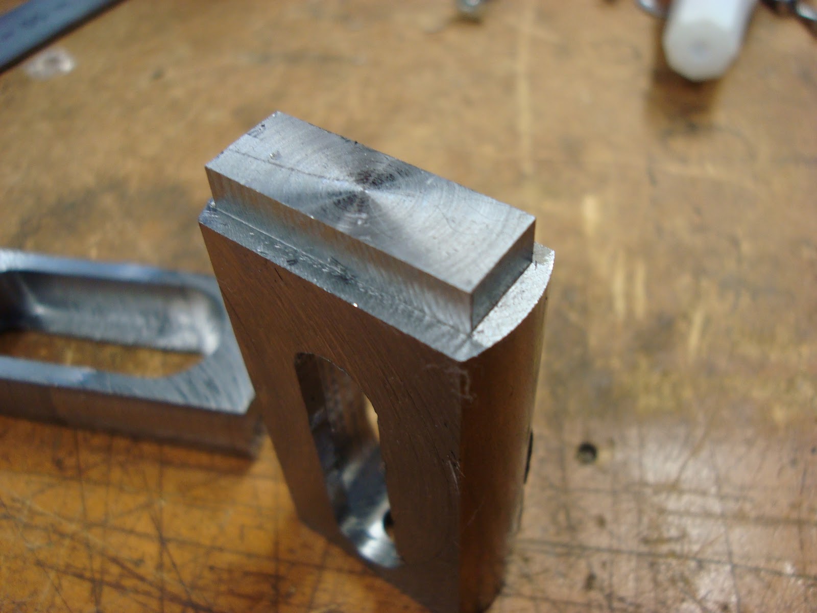
The part is then flipped over and rested on a set of parallels to keep it.... parallel :P while the other side was machined.
And the part at this stage with a piece of the original rod.

After making two identical pieces shown above it was then time to make the first slot for the axle to go through. There needs to be two - one 19mm and one 10mm (the axle diameter). so the 10mm was done first.
One of the best tips when it comes to milling is that drilling removes the most material for per unit of time of nearly every tool. So for an operation like slotting drilling a series of holes reduces tool wear infinitely and allows the end mill to basically finish the slot off.
Here the stock is being drilled with a center drill before final drilling to 10mm, then the completed holes with a 10mm carbide end mill in the collet chuck ready for finishing. The digital read out makes this a doddle.


First pass with the end mill. Not tempting fate with steel the cut depth was only 2mm. With coolant it chewed through like it was nothing.

And all done. The finish is very ordinary because i just did the slot in one pass. The proper way is to drill the holes smaller to say 8mm then make a 1mm cut either side of the slot to finish it off. Given how long it took to mill the single slots and the fact accuracy wasnt critical, i wasnt too concerned.


Next was the big slot the adjuster itself sits in. the cad called for 20mm but the closest end mill was 19mm so that was used instead.
I didnt grab a picture of it but i used an 18mm roughing bit to do the initial slot then finished it off with the 19mm using the aforementioned process. Heres the first pass at 2mm depth.

And at final depth, but using a standard carbide tool to do some gentle cutting passes for a good surface finish.

Done :) the finish on the 19mm slot is great as you can see, the 10mm not so much so, so that shows why you need to cut the slot undersize initially. Mind the rough edges at this stage, it still needs cleaning up on the mill.

After completing the 2nd one it was back into the mill to clean up all those nasty edges and start on the "nubs". These parts will fit into the ends of the box section to provide some strength in addition with the welds and also to help locate them while they are welded.
Nothing too special with the process. just cut down with the 10mm end mill. Heres the finished part.

Nearly there! The chain adjusters themselves were next to be made. nothing too hard. drilled out some 20mm rod to 10mm, then turned the outside diameter to 19mm and parted it off. The edges were then rounded off with a knife tool as seen here.

Drilling the edges and tapping them for M6 threads means the machining is done! The finish is hardly perfect but for a compartively small mill its more than acceptable to me.


Back at headquarters the pieces were lined up and welded with the TIG. And here they are all welded in. I reckon they look pretty damn good :)


All that remains now is to get a new decent axle and make some axle protectors for the ends. Then the spacers will also need to be redone and the chassis painted/powder coated.
So thats it! Hopefully your all still awake by the end of this :p
Now i need to go pick the swarf out of my hair.. ughh..

No comments:
Post a Comment